Boards
Amperes Minion Board
The Amperes minion board is connected to the main power cable that powers the electrical loop using the Shunt Resistor.
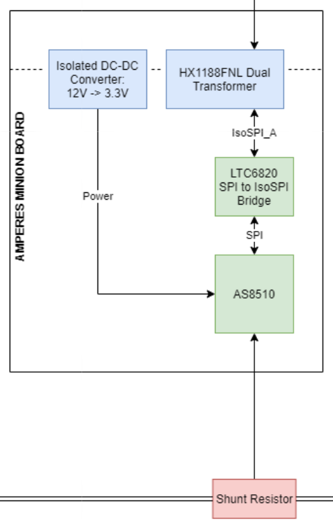
AS8510 Block Diagram
Overview
- Brief Description/Purpose:
This board monitors the current and temperature of the BPS system.
Pertinent Regulations
Regulation |
Description of Regulation |
How Regulation is Met |
8.3 |
All batteries must have protection circuitry
appropriate for the battery technology used.
Proof is required at scrutineering that the
protection System is functional and meet
manufacturer’s specifications… All
protection circuitry should be contained in
the battery enclosure per Reg 8.4.
|
This board monitors the current/temperature
of the battery and sends both measurements
back to the BPS Leader. Then, the BPS system
determines if these measurements are within
normal range and if not, will take
apropriate action.
|
8.3.A.5 |
System in which measurements are constantly
monitored and where actions are taken
immediately without operator intervention
to open the Main Power Switch should a
battery Protection Fault occur. Any
manual clearing process is required by the
driver with the vehicle not in motion and
only after faults have been verified clear
by the protection system.
|
This board sends current and temperature
measurement back to the BPS leader
periodically. This helps the BPS Leader board
determine when a Battery protection Fault
occurs and take appropriate actions.
|
Context
Location of the Board: Battery Box
List of I/O and Connections:
- Power +12 V
Input from BPS Leader Board
- Power GNDPWR
Input from BPS Leader Board
- Signal ETS (External Temperature Sensor)
Input from Shunt Resistor Board
- Signal RSHL (Negative Differential input for current channel)
Input from Shunt Resistor Board
- Signal RSHH (Positive Differential input for current channel)
Input from Shunt Resistor Board
- Signal TX+/TX-
Output to BPS Leader Board
Schematic
Main
- What does this circuit do?
Monitors current and temperature of the BPS system.
- Why do we need it?
This board physically measures the temperature and current from the Shunt Resistor Board and then, sends the measurements back to the BPS Leader Board.
- List of Circuit Components
- LTC2315
Description: Shunt-based sensing/processing IC
Why is it necessary: Measures input current and temperature and sends it to the LTC6820 using SPI.
Justification for selection of specific part:This device has higher accuracy for a larger range, compared to other products.
- Associated passives/components:
J1 Shunt Conn (1x4 Connector)
- RO-123.3S_HP
Description: DC Converter
Why is it necessary: Converts +12V input into +3.3V, GNDPWR input to GND while maintaining the isolation of the input power.
Justification for selection of specific part: Standard component
- LTC6820
Description: isoSPI Communications Interface
Why is it necessary: Converts 4-wire SPI signal output from AS8510 into 2-wire isoSPI signal
Justification for selection of specific part: Standard component
- HX1188FNL
Description: Signal Transformer
Why is it necessary: Isolates the isoSPI signal to be sent to the BPS Leader Board
Justification for selection of specific part: Standard component
- Associated passives/components:
J2 Leader Conn (1x4 Connector)
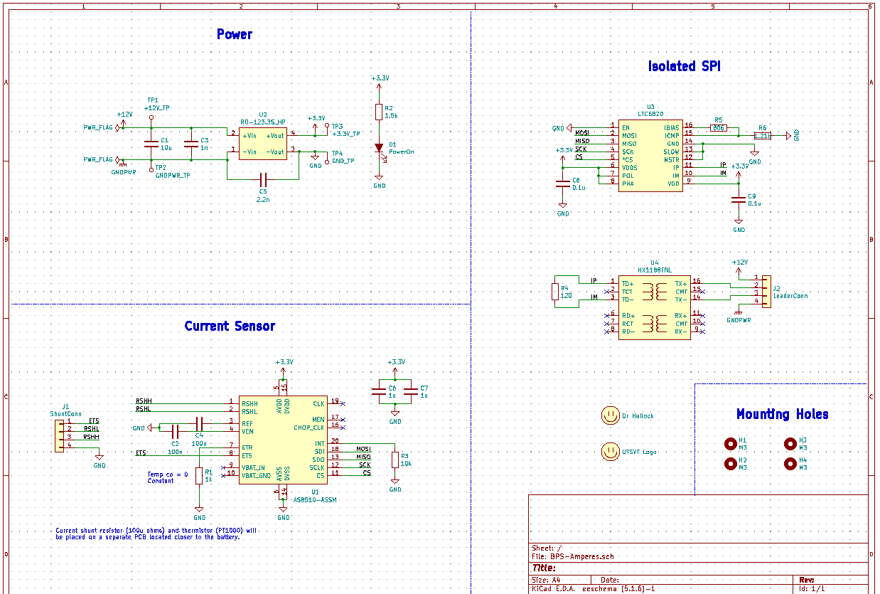
Amperes Minion Board Schematic
Dimensions: 58.250mm by 30.250mm
- Requirements/Constraints:
The HX1188FNL needs to be isolated, as in it cannot be placed on a GND or Power layer. So a keep-out area was used around the HX1188FNL.
Connectors must be placed on opposite sides of the board. This will allow all the connections to fit on the board.
- Design Choices:
The board was kept at a small size to conserve space
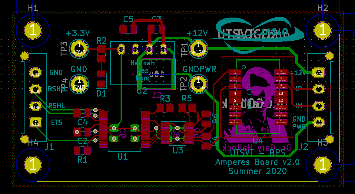
Amperes Minion Board Layout
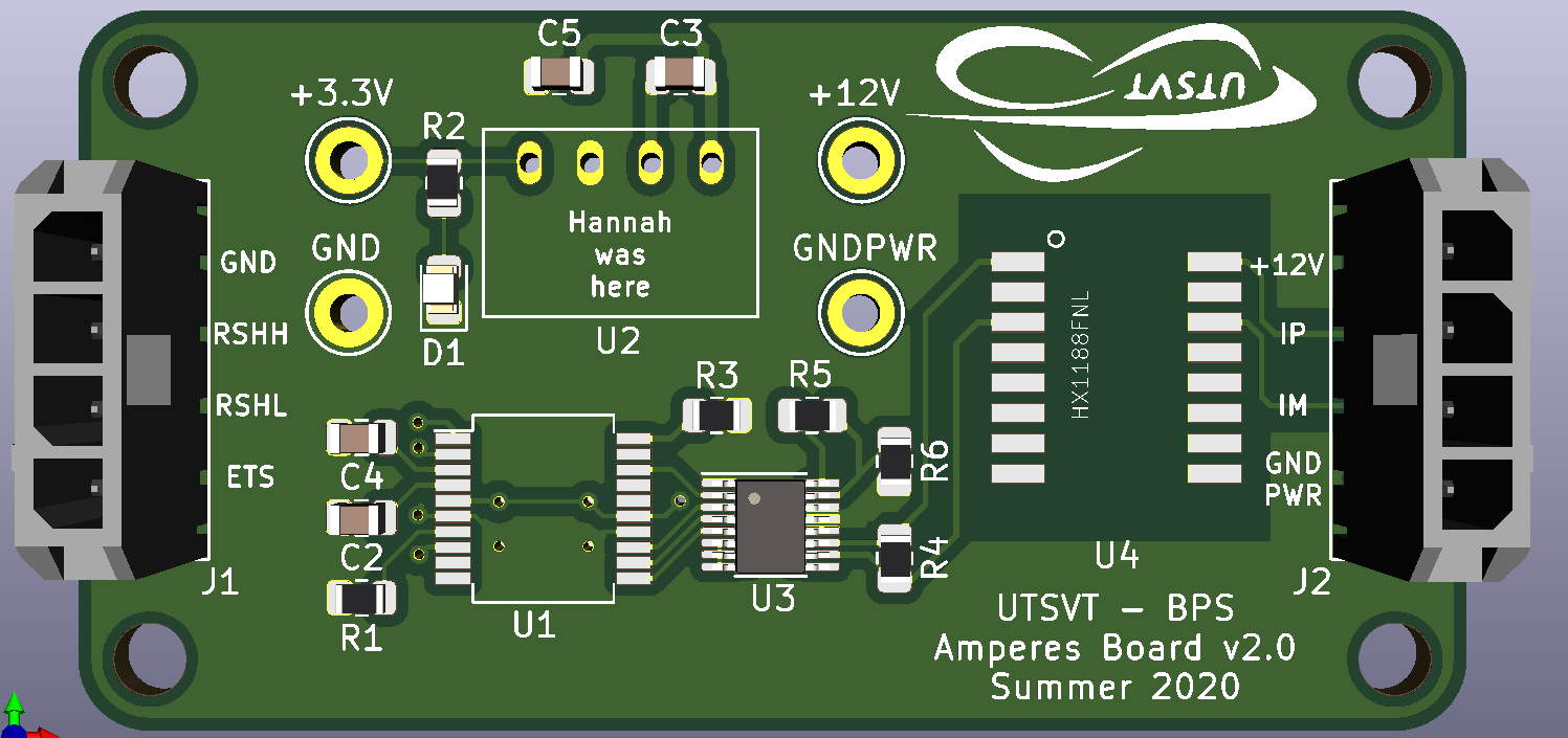
Amperes Minion Board Render
Amperes Minion Board Render
Fan Board
Overview
- Brief Description/Purpose:
The purpose of this board is to set the speed of the fans that will be used to cool the battery pack. It receives signals from the Leader Board and sends them across a MOSFET that switches the fan on or off.
Pertinent Regulations
Regulation |
Description of Regulation |
How Regulation is Met |
8.4.D |
Battery enclosures may be equipped with a
forced ventilation system. Such ventilation
systems must pull exhaust to the exterior of
the solar car and must be directly connected
to the exterior of the vehicle away from any
airstream that may reach the driver. The
ventilation system shall be powered by the
battery system. In the event of a Battery
Protection Fault, provisions should be made
to power this fan from the Supplemental
battery.
|
The BPS fan board is powered by the battery
system and in the event of a battery protection
fault it’s powered by the supplemental battery.
|
Context
Location of the Board: With the BPS in the battery box
List of I/O and Connections:
Schematic
Main
- What does this circuit do?
They control the fan’s speed for cooling the battery pack.
- Why do we need it?
This board makes sure the batteries don’t heat up by controlling the speed of the fans based on the temperature.
- List of Circuit Components
- Connector_Molex:Molex_Micro-Fit_3.0_43045-0612_2x03_P3.00mm_Vertical (LDRBRDConn)
Description: connects the leader board to fan board
Why is it necessary: so the fans can be supplied power
Justification for selection of specific part: this connector provides the right amount of power and connections for all fans being used
- Associated passives/components:
4 different BUK9M34-100EX
- BUK9M34-100EX(4)
Description: a MOSFET that will switch the fans off and on
Why is it necessary: so the fans can be set to certain speeds by turning them on and off at varying rates
Justification for selection of specific part: this part is used over others because of Q101 compliant, its suitable for thermally demanding environments, and true logic gate with VGS(th) rating of greather than 0.5V at 175°C
- Associated passives/components:
4 different diodes, Molex_MicroFit3.0_1x2xP3.00mm_PolarizingPeg_Vertical and the LDRBDConn above.
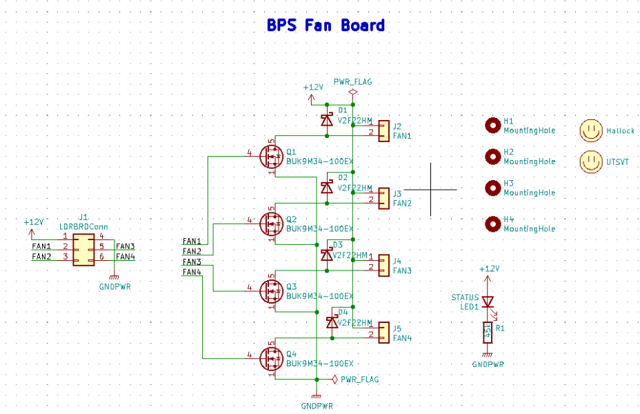
Fan Board Schematic
Dimensions: 45.00mm by 34.50mm
- Requirements/Constraints:
We chose flyback diodes to be used to prevent voltage spikes from entering into the leader board (since the pulsing fans can cause the spikes).
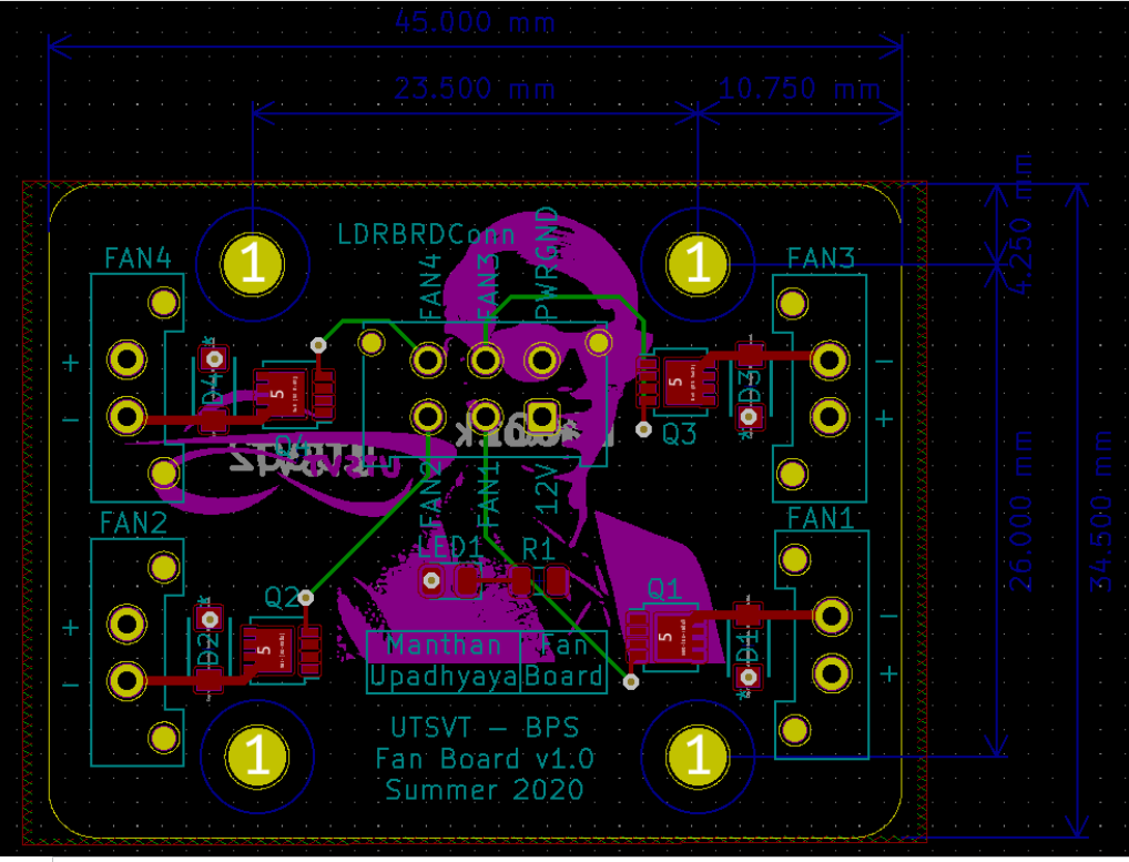
Fan Board Layout
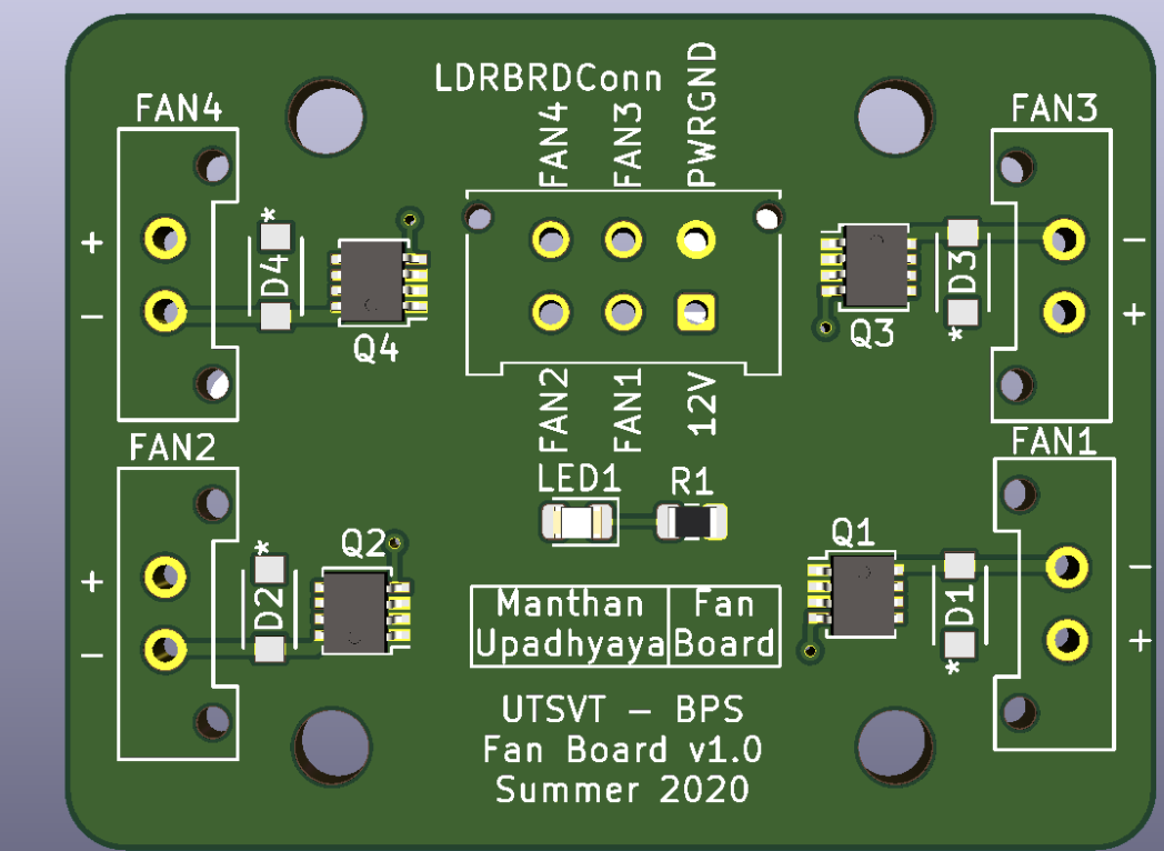
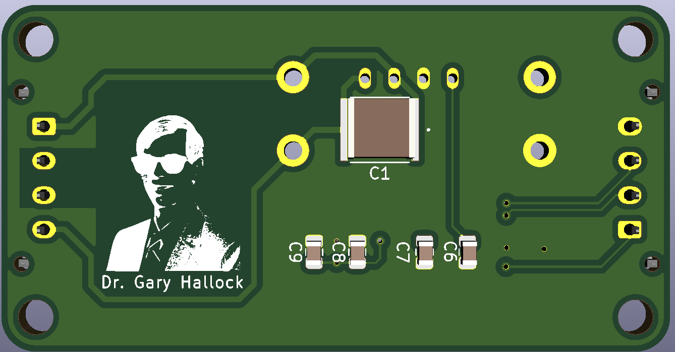
Fan Board Render
Display Board
Overview
- Brief Description/Purpose:
The purpose of this board is to display messages from the CAN interface on the E-Ink display for debugging.
Pertinent Regulations
Regulation |
Description of Regulation |
How Regulation is Met |
8.3.B.2 |
All supplemental batteries must have at a
minimum Passive Protection for under voltage
where charging occurs remote to the solar
vehicle unless they are primary cells.
Active Protection is required if charging is
within the solar vehicle. No Secondary
Lithium battery types shall be used for the
Supplemental Battery unless the Supplemental
Battery is powering a commercially procured
component such as a cell phone or laptop and
the Supplemental Battery was intended for
this purpose.
|
The “SUPP CHECK” (Supplemental Check) LED |
Context
Location of the Board: On a movable arm mount attached to the south end of the board. Mounted near the driver.
List of I/O and Connections:
- Power GNDPWR
Input from car power connector
- Power +12V
Input from car power connector
- Power +5V
Output from power distribution subsheet
- Power +3.3V
Output from power distribution subsheet
Schematic
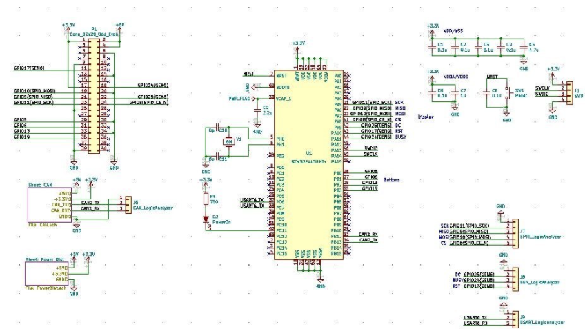
Main
- What does this circuit do?
This circuit makes connections from the microcontroller to the E-Ink Display and logic analyzer pins.
- Why do we need it?
We need this circuit in order for debugging (CAN messages on the E-Ink display and logic analyzer pins).
- List of Circuit Components
- STM32F413RHTx
Description: Microcontroller
Justification for selection of specific part: Standard component
- Associated passives/components:
Bypass capacitors
- 8 MHz External Crystal Oscillator: used to set the Phase Lock Loop (PLL) and the system core frequency (CPU processor speed)
Using an external clock ensures for precision, which is important in a safety-critical system like the BPS.
Reset button
SWD Programming Pins
- Logic Analyzer Pins (2.54 mm headers)
Description: The logic analyzer pins serve to easily test the board to check proper functionality of the board.
Why is it necessary: This allows for testing to be much easier since we can monitor. what occurs to these signal lines through these pins
Justification for selection of specific part: Standard component
- Associated passives/components:
SPIO Analyzer Pins 1x5: PA5, PA6, PA7, PA8, GND
GEN Analyzer Pins 1x4: PA9, PA10, PA11, GND
USART Analyzer Pins 1x3: PC6, PC7, GND
CAN Analyzer Pins 1x3: PB12, PB13, GND
- E-Ink Display:
Description: Display screen.
Why is it necessary: CAN messages will be displayed on this screen.
Justification for selection of specific part: This display doesn’t consume much power.
- Associated passives/components:
2x20 Connector
- 2x20 Connector (2.54mm)
Description: Connects the STM to the E-Ink display.
Why is it necessary: Allows the E-Ink display to show CAN messages.
Justification for selection of specific part: Standard component
- Associated passives/components:
Buttons: PB0, PB1, PB2, PB3
SPIO: PA5, PA6, PA7, PA8
GEN: PA9, PA10, PA11
- Reset button
Description: Resets the STM microcontroller.
Why is it necessary: Used in case the board needs to be reset.
Justification for selection of specific part: Standard component
List of Subsheet I/O
- Power +5V:
Input from power distribution subsheet
- Power +3.3V:
Input from power distribution subsheet
- CAN TX:
Input from CAN subsheet
- CAN RX:
Input from CAN subsheet
Display Board Subsheet Schematic
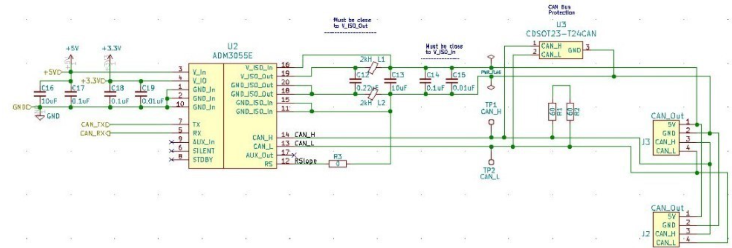
CAN
- What does this circuit do?
This circuit sets up the CAN interface between microcontrollers.
- Why do we need it?
We need this circuit in order for debugging messages to be transmitted between microcontrollers.
- List of Circuit Components
- ADM3055E:
Description: This is an isolated CAN physical layer transceiver with integrated isolated DC to DC converters.
Why is it necessary: It provides isolation between the CAN controller and the main bus.
Justification for selection of specific part: Standard component
- Associated passives/components:
Bypass capacitors
- CDSOT23-T24CAN:
Description: This component provides ESD and surge protection for CAN transceivers.
Why is it necessary: CAN bus protection.
Justification for selection of specific part: Standard component
- Associated passives/components:
External resistors
List of Subsheet I/O
- Power +5V:
Input from power distribution subsheet
- Power +3.3V:
Input from power distribution subsheet
Display Board CAN Subsheet Schematic
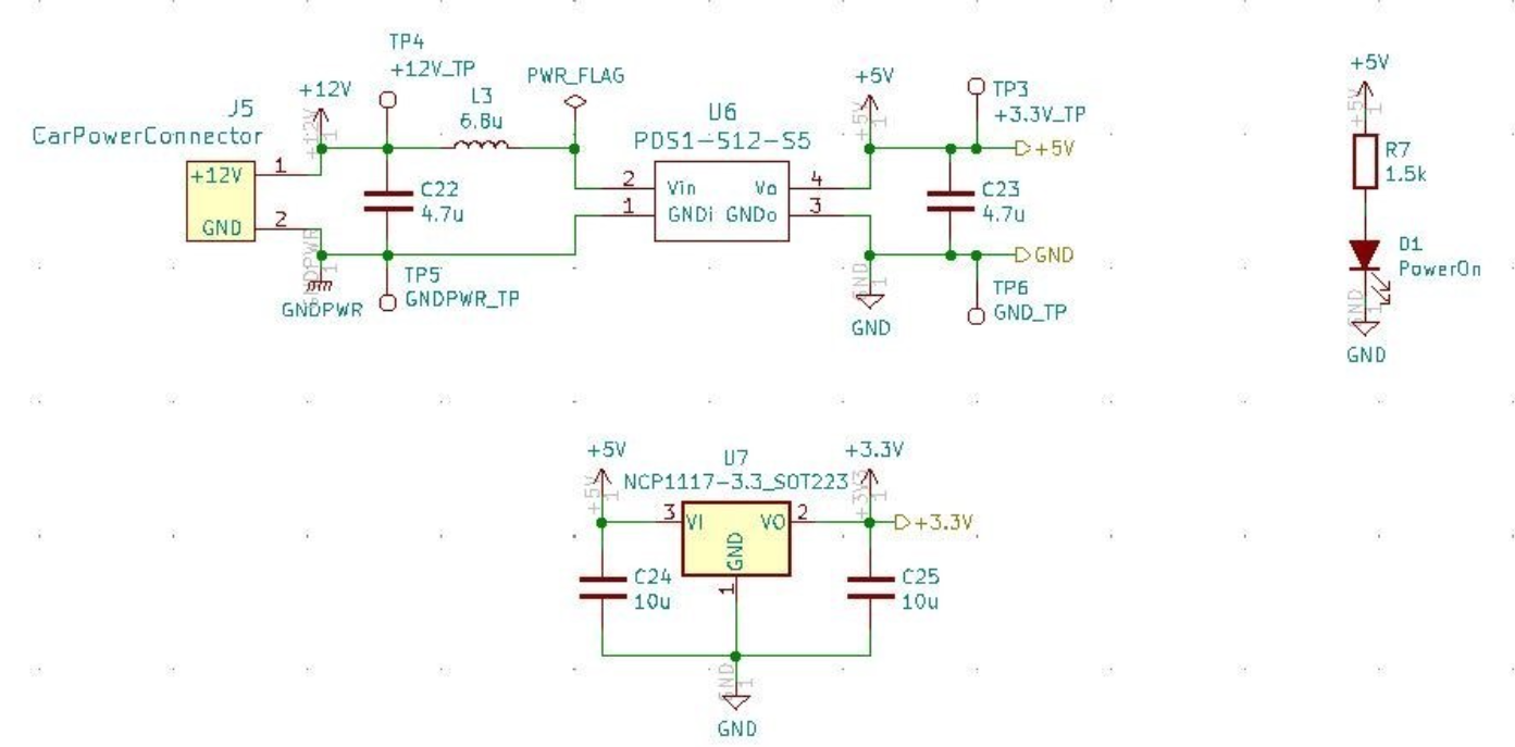
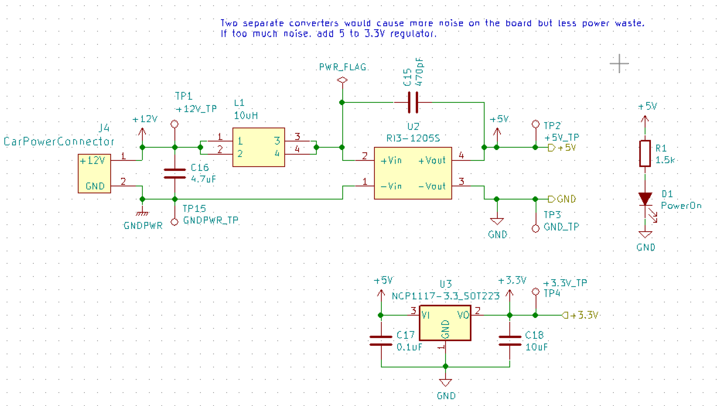
Power Distribution
- What does this circuit do?
This circuit takes the +12V power line from the car power connector and takes it down to +5V and +3.3V.
- Why do we need it?
We need this circuit in order to have stable +5V and +3.3V power lines for the rest of the board.
- List of Circuit Components
- PDS1-S12-S5:
Description: DC-DC converter.
Why is it necessary: Converts DC +12V to DC +5V.
Justification for selection of specific part: Standard component
- Associated passives/components:
Bypass capacitors
Inductor
- NCP1117:
Description: Low-dropout voltage regulator.
Why is it necessary: Uses +5V to produce an output voltage of +3V.
Justification for selection of specific part: Standard component
- Associated passives/components:
Bypass capacitors
List of Subsheet I/O
- Power +12V:
Input from car power connector
- Power +5V:
Output from PDS1-S12-S5
- Power +3.3V:
Output from NCP1117
Display Board Power Distribution Subsheet Schematic
Layout
Dimensions: 56.00mm x 91.46mm
- Requirements/Constraints:
The e-Ink display acts as a shield and lays on the board, so components with a tall height can’t be placed by the display
The LEDs must be visible and not covered by the e-Ink display
- Design Choices:
The parts are organized in sections, with the power distribution system in the bottom left and the CAN connections on the center-right side of the board.
All the logic analyzer pin headers are now separate. They were formerly all in one bigger pin header, but have now been split apart to make traces shorter and neater.
The CAN connectors and car power connectors were placed on the south end of the board so that the wires connecting to them could go through the arm mount.
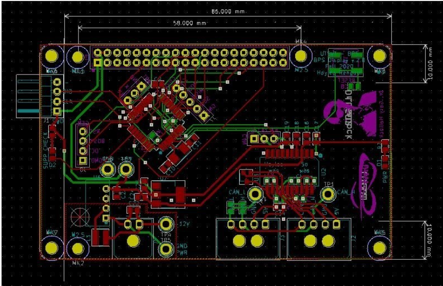
Display Board Layout
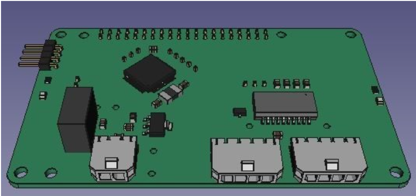
Display Board Render Top
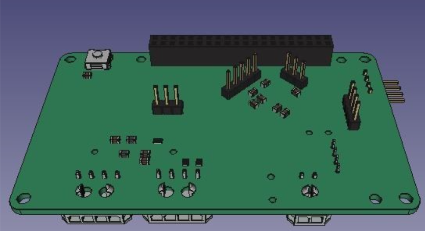
Display Board Render Bottom
Leader board
Connectors
The Leader board uses the STM32F413 microcontroller. The board requires seven connectors:
One 2-pin power connector (+12V, PWRGND)
One 2-pin error light connector (+12V, PWRGND)
One 4-pin contactor connector (+12V, PWRGND, aux1, aux2)
One 4-pin Amperes board connector (+12V, PWRGND, IP, IM)
One 4-pin CAN connector (isolated +5V, isolated GND, CAN high, CAN low)
One 2-pin Minion connector (IP, IM)
One 2x4-pin fan connector (4x +12V, 4x PWRGND)
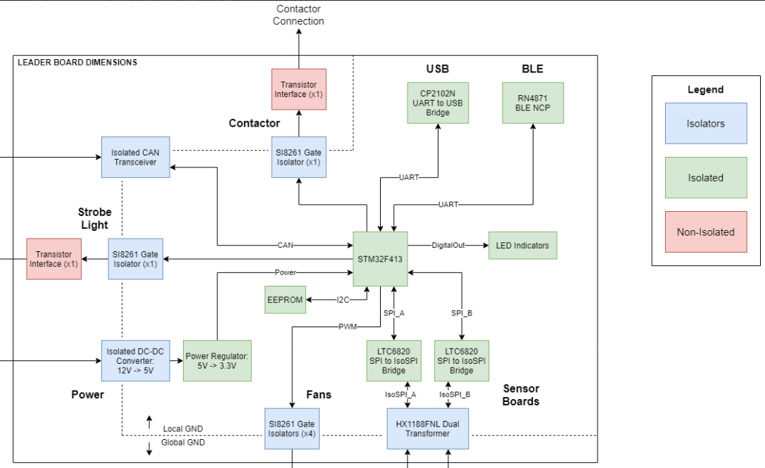
Leader Board Block Diagram
Microcontroller
The STM32F413 requires bypass capacitors and uses an 8MHz clock. To program the STM32F413, pins are connected to a 1x4 header to use the SWD programming protocol.
The reset button allows you to avoid powering the BPS off to reset it.
Note
You can configure the system to reset every time you use the Keil IDE to program it.
For more information, see the STM32F413 datasheet.
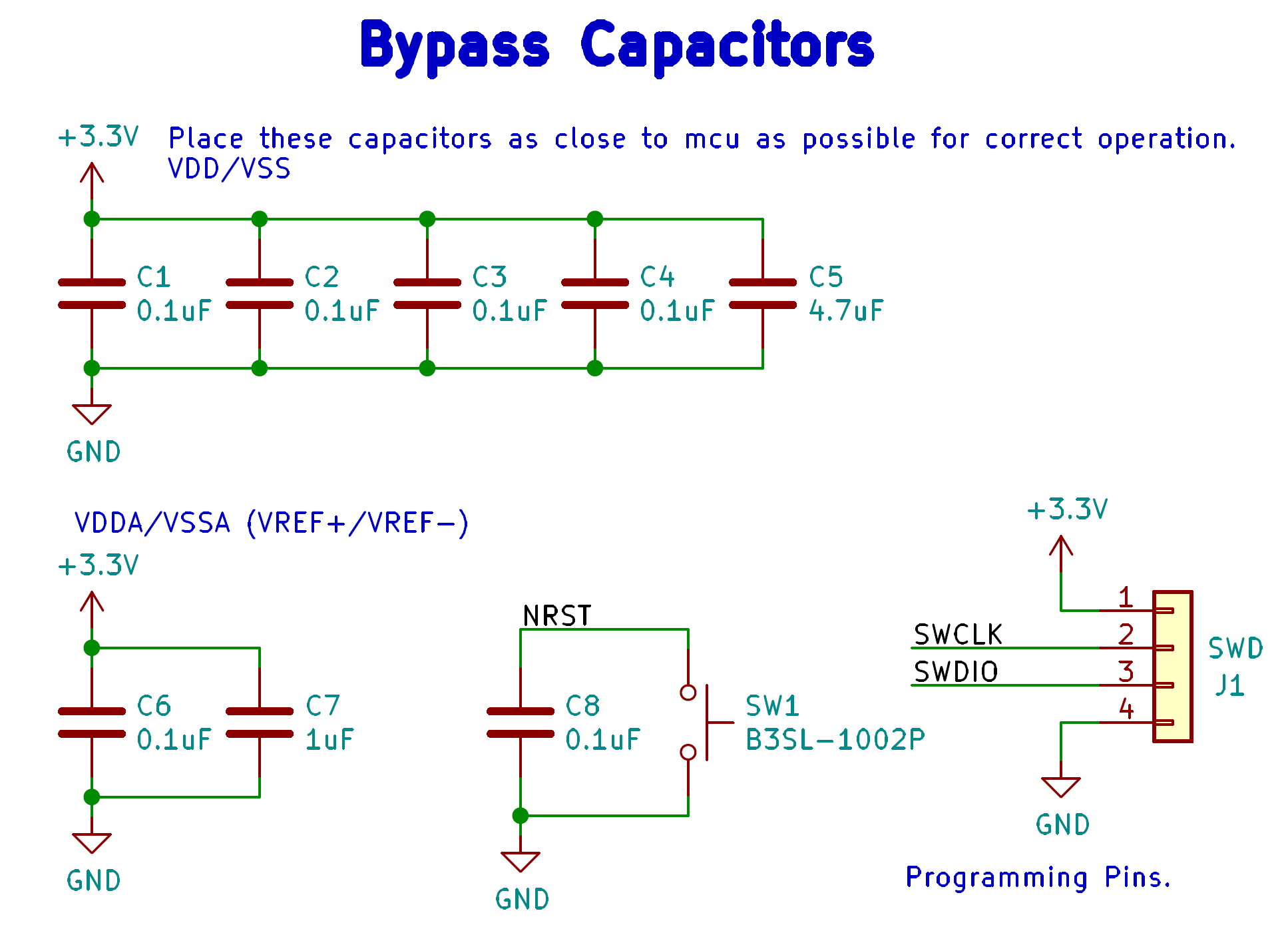
STM32F413 bypass capacitors
Clock
The system’s RTC is sourced from a low-power crystal oscillator. The crystal is used to set the PLL, which sets the system core frequency (CPU clock speed). The controller supports a range of frequencies, but the default is 8MHz.
The MCU has an alternate internal clock that saves power consumption at the cost of precision. Since this system is safety critical, the external 8MHz crystal was added.
Note
The internal and external clocks were not tested against each other.
Capacitors
Capacitor values are set based on the crystal’s load capacitance and the capacitance of the whole board. The crystal and capacitor should be as physically close to the MCU as possible to avoid signal drift.

STM32 crystal layout
Power connector
The Leader board gets a 12V power supply. The voltage must be dropped to power the MCU and components. The total voltage required for all the components is +3.3V and +5V.
DC-DC converter
An isolated DC-DC converter (RI3-1205S) converts the +12V input to +5V. The +12V input will be isolated from the +5V output. The Leader board must use the correct grounds to maintain isolation.
A switching regulator (NCP1117) converts the +5V input to +3.3V. This does not need isolation because the +5V input and corresponding grounds are already isolated from the +12V line.
Leader board power distribution
Voltage & Temperature Minion Board
Overview
- Brief Description/Purpose:
There are two temperature sensors for each battery module with a module minion board for each of the four rows. Each board measures up to 12 battery modules and 16 temperature sensors, but is configured for eight modules and 16 sensors by default. The temperature sensors are placed as inputs to a mux and the mux switches between all of them.
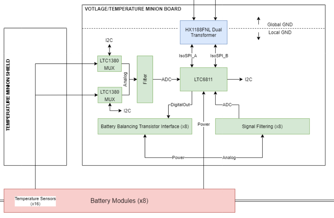
LTC6811 Block Diagram
Pertinent Regulations
Regulation |
Description of Regulation |
How Regulation is Met |
8.3.A.5 |
System in which measurements are constantly
monitored and where actions are taken
immediately without operator intervention to
open the Main Power Switch should a battery
Protection Fault occur.
|
The Minion board constantly takes voltage and temperature
measurements of the battery modules and transmits data
back to the leader board.
|
Context
Location of the Board: Battery box
List of I/O and Connections:
- Leaderboard/Minion Board Input (Isolated SPI bus)
Input from BPS Leader Board, tells the Minion board when to gather measurments form the batteries.
- LeaderBoard/Minion Board Output (Isolated SPI bus)
Outputs to the leaderboard, transmits voltage and temperature readings from the battery modules.
- Voltage Connectors
Input from the battery modules, transmit voltage from each battery module. The IC also uses this voltages to power itself.
- Minion Shield Power
5V output from the LTC6811 to the Minion Shield board. This is used to power the temperature sensors.
- Temperature Input
Input from the Minion Shield board, transmits temperature data.
Schematic
Main
- What does this circuit do?
This circuit measures the voltages and temperatures of each battery module and sends the data to the leader board when prompted.
- Why do we need it?
Regulations stipulate that the voltages and temperatures of the battery modules must be monitored at all times.
- List of Circuit Components
- 2 Molex Micro-fit 3.0 1x07 3.00mm Horizontal
Description: Each connector allows for seven connections to the battery modules
Why is it necessary: Sends the voltages of the battery modules to the IC
Justification for selection of specific part: Standard component
- Associated passives/components:
12 bypass capacitors
12 inductors
12 PMOS transistors
12 resistors connecting to the source of the PMOS transistors
- 2 Molex Micro-fit 3.0 1x10 2.54mm Vertical
Description: Connects to temperature sensors on the Minion Shield board
Why is it necessary: Allows the Minion Board to retrieve temperature data from Minion Shield board
Justification for selection of specific part: Standard component
- Associated passives/components:
LTC1380
100 nF decoupling capacitor
- LTC1380
Description: Analog 1:8 MUX. There are 2 on the board, one for each temperature sensor connector.
Why is it necessary: Since there are a limited number of AUX pins, an analog MUX connects the temperature sensors to GPIO1 of the ADC.
Justification for selection of specific part: This part is a single-ended 8-channel MUX, which fits the need for a 1:8 MUX.
- Associated passives/components:
Two 4.7kohm resistors, one 10kohm resistor
LTC6255
- LTC6255
Description: Op Amp
Why is it necessary: to amplify the signal from the sensors
Justification for selection of specific part: This op amp is listed in the datasheet for LTC6811 as a component to use to amplify the signal (from the sensors) ahead of its transmission to LTC6811.
- Associated passives/components:
100 ohm resistor
Decoupling capacitor
- LTC6811
Description: Integrated circuit that measures the voltages and temperatures of the battery modules
Why is it necessary: Takes the voltage and temperature inputs and transmits the data to the leader board
Justification for selection of specific part: Standard IC for battery management systems in industry
- Associated passives/components:
Switch (If the IC won’t be used for an extended period of time, it can be turned off with this switch.)
Resistors: 806 ohm, 1.2kohm, Two 100 ohm
Bypass capacitors
HX1188FNL
LTC6255
Regular SPI Connector (1x5 2.54mm Vertical)
DTEN Configuration Connector (1x3 2.54mm Vertical)
Iso Configuration Connector (1x3 2.54mm Vertical)
- HX1188FNL
Description: Single port surface mount magnetics
Why is it necessary: Connects to the input and output connectors to the IPA and IMA connections, respectively, on the LTC6811.
Justification for selection of specific part:
- Associated passives/components:
Two 120 ohm resistors
LTC6811
- 1 Molex Micro-fit 3.0 1x5 2.54mm Vertical
Description: Connector for the Regular SPI connection.
Why is it necessary: Connects to the IPA, IMA, SDI, and SDO connections on the LTC6811.
Justification for selection of specific part: Standard component.
- Associated passives/components:
5.1k pull-up resistor (for SDO)
LTC6811
- 2 Molex Micro-fit 3.0 1x3 2.54mm Vertical
Description: One connector is for Iso configuration and one connector is for DTEN configuration.
Why is it necessary: Connects to the ISO and DTEN connections on the LTC6811.
Justification for selection of specific part: Standard component
- Associated passives/components:
LTC6811
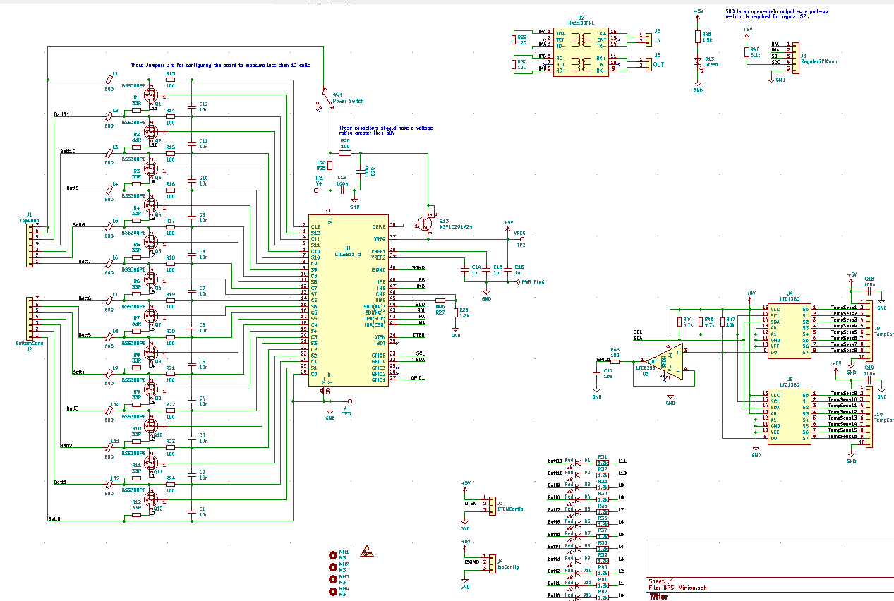
Minion Board Schematic
Dimensions: 66.00mm by 85.00mm
- Requirements/Constraints:
Connectors to the battery modules are placed vertically on the right to make use the connections sequential and more intuitive.
Communication connections to the Leader Board are placed on the right side opposite the battery connections.
- Design Choices:
The MUXs and connectors to the temperature sensors were placed on the Minion Shield board to keep the board smaller and more compact
LTC 6811 was placed at the center of the board to minimize distance to the outlying components.

Minion Board PCB
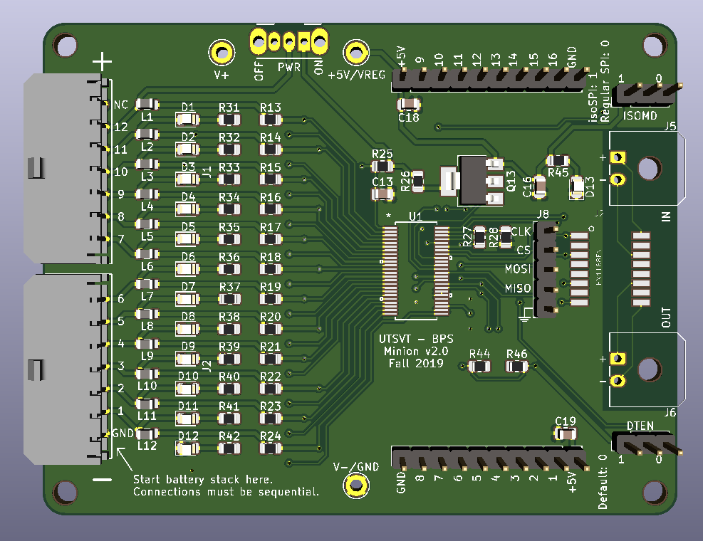
Front of Minion Board render
Back of Minion Board render
BPS Minion Shield
Overview
- Brief Description/Purpose:
The Minion Shield board is a shield for the Module Minion board. The board connects 16 temperature sensors to the Minion board, saving space on the actual Minion board.
Pertinent Regulations
Regulation |
Description of Regulation |
How Regulation is Met |
8.3 |
All batteries must have protection circuitry
appropriate for the battery technology used.
Proof is required at scrutineering that the
protection System is functional and meet
manufacturer’s specifications… All
protection circuitry should be contained in
the battery enclosure per Reg 8.4.
|
This board connects to the temperature sensors,
which will check for the fault conditions that
concern temperature (Max charging temperature
of 45 C and discharging temperature bounds of
60 C).
|
8.3.A.5 |
System in which measurements are constantly
monitored and where actions are taken
immediately without operator intervention
to open the Main Power Switch should a
battery Protection Fault occur. Any
manual clearing process is required by the
driver with the vehicle not in motion and
only after faults have been verified clear
by the protection system.
|
This board connects to the temperature
senors, which take temperature measurements
and allow the Module Minion board to
constantly monitor them without
operator intervention
|
Context
Location of the Board: The board is stacked on the Module Minion board.
List of I/O and Connections:
- Power +5 V
Input from Module Minion board
- GND
Input from Module Minion board
- TempSens (1-16)
input from a temperature sensor (using LMT87
output to the Module Minion board
Schematic
Main
- What does this circuit do?
This circuit connects 16 temperature sensors to the Minion board.
- Why do we need it?
The purpose of this circuit is to house the temperature sensor connectors in order to save space on the Minion board.
- List of Circuit Components
- 16 1x3 Molex Microfit-3.0 Connectors
Description: Each connector connects a temperature sensor to the Module Minion board.
Why is it necessary: It allows the temperature sensors to connect to the Module Minion board without having them directly on the Module Minion board.
Justification for selection of specific part: Standard component
- Associated passives/components:
100 nF Capacitor (decoupling capacitor for +5V connection)
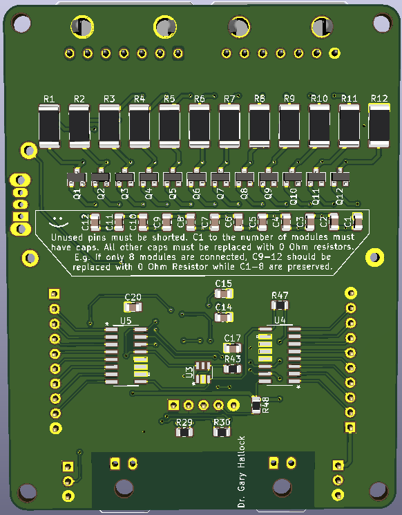
- 2 Male 2.54mm Pitch 1x10 Pin Headers
Description: Each male 1x10 pin header connects to 8 temperature sensor signals.
Why is it necessary: These pin headers allows this board to stack on the Module Minion board.
Justification for selection of specific part: Standard component
- Associated passives/components:
100 nF Capacitor (decoupling capacitor for +5V connection)
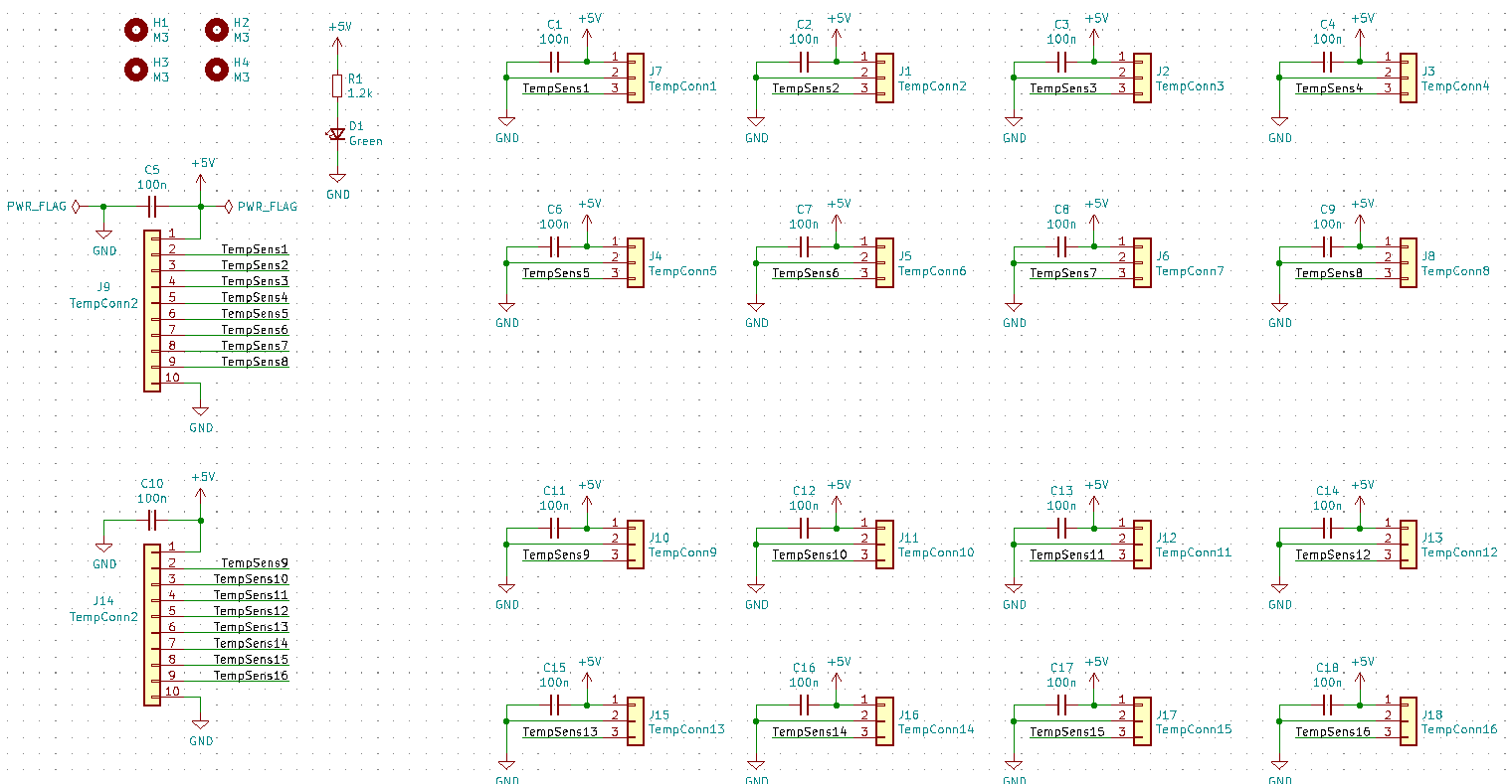
BPS Minion Shield Board Schematic
Dimensions: 85.00mm by 66.00mm
- Requirements/Constraints:
The male pin headers are on the top and bottom edges of the board so that they can properly connect/stack on the Module Minion board.
The board curves in on the left because the battery stack on the Module Minion board occupies that area.
- Design Choices:
The temperature sensor connectors are staggered and symmetric about the midline of the board.
All capacitors are on the back of the board.
There is a power LED in the bottom right of the board.
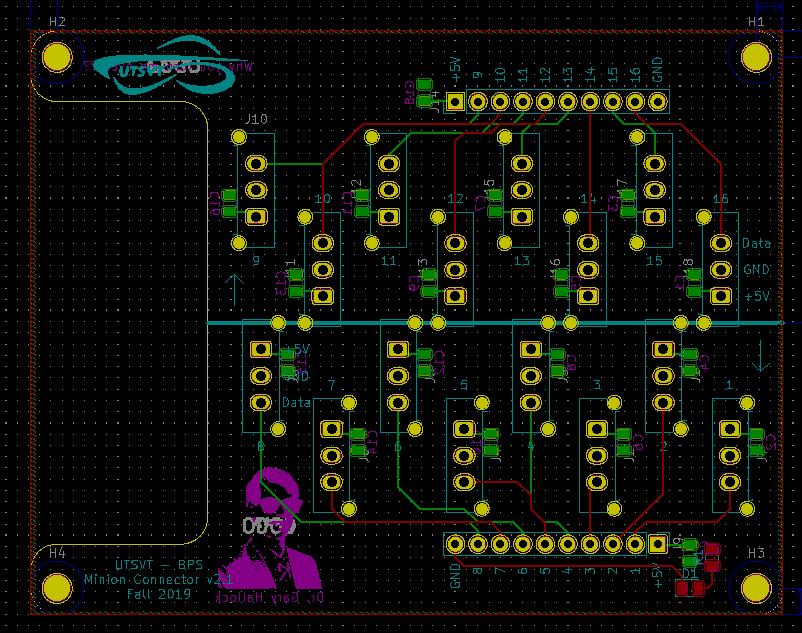
BPS Minion Shield Board Layout
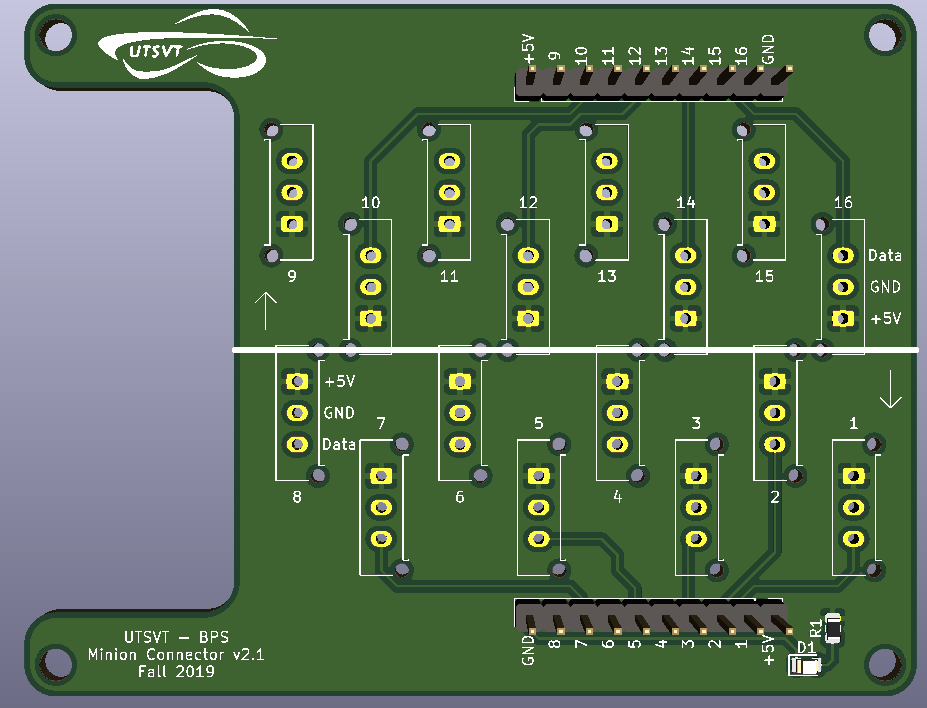
Front of BPS Minion Shield Board Render
Back of BPS Minion Shield Board Render
BPS Shunt Resistor Board
Overview
- Brief Description/Purpose:
This board holds the shunt resistor that allows the BPS Amperes Board to measure current and temperature. This board sends the temperature and current quantities to be measured over to the BPS Amperes Board.
Pertinent Regulations
Regulation |
Description of Regulation |
How Regulation is Met |
8.3 |
All batteries must have protection circuitry
appropriate for the battery technology used.
Proof is required at scrutineering that the
protection System is functional and meet
manufacturer’s specifications… All
protection circuitry should be contained in
the battery enclosure per Reg 8.4.
|
This board helps in monitoring the current/
temperature of the battery. Then, the BPS
system determines if these measurements are
within normal range and if not, will take
appropriate action.
|
8.3.A.5 |
System in which measurements are constantly
monitored and where actions are taken
immediately without operator intervention
to open the Main Power Switch should a
battery Protection Fault occur. Any
protection faults will latch such that a
manual clearing process is required by the
driver with the vehicle not in motion and
only after faults have been verified clear
by the protection system.
|
This board sends current and temperature
quantities to be measured to the BPS Amperes
board constantly. Once measured, this
information is sent to the BPS Leader board
and helps determine when a Battery protection
on fault occurs.
|
Context
Location of the Board: Battery Box
List of I/O and Connections:
- Power GND
Input from BPS Amperes Board
- Signal RSHL
Output to BPS Amperes Board
- Signal RSHH
Output to BPS Amperes Board
- Signal ETS
Output to BPS Amperes Board
Schematic
Main
- What does this circuit do?
This board sends the temperature and current quantities to be measured over to the BPS Amperes Board.
- Why do we need it?
This allows the BPS Amperes Board to measure the current and temperature of the BPS system.
- List of Circuit Components
- Battery Shunt Resistor
Description: This part is connected to the high voltage line running out of the battery pack and produces the signals RSHL and RSHH
Why is it necessary: This part is necessary because it sends the temperature and current quantities to be measured over to the BPS Amperes Board.
Justification for selection of specific part: This part is used because it provides a more accurate way to measure current, compared to previous methods like the Hall-effect. While this part is not galvanically isolated, the BPS Amperes Board is able to isolate the current measurement before it’s sent to the BPS Leader Board. Thus, all together, this method using a shunt resistor provides an accurate way to provide current and temperature measurements while maintaining the power isolation in the BPS Leader Board.
- Thermistor
Description: This part is used to measure temperature.
Why is it necessary: This part helps the shunt resistor make an accurate temperature measurement.
Justification for selection of specific part: This part is used because it meets the requirements of the AS on the BPS Amperes Board and this part fits on the board more easily due to its Surface Mount 0805 size.
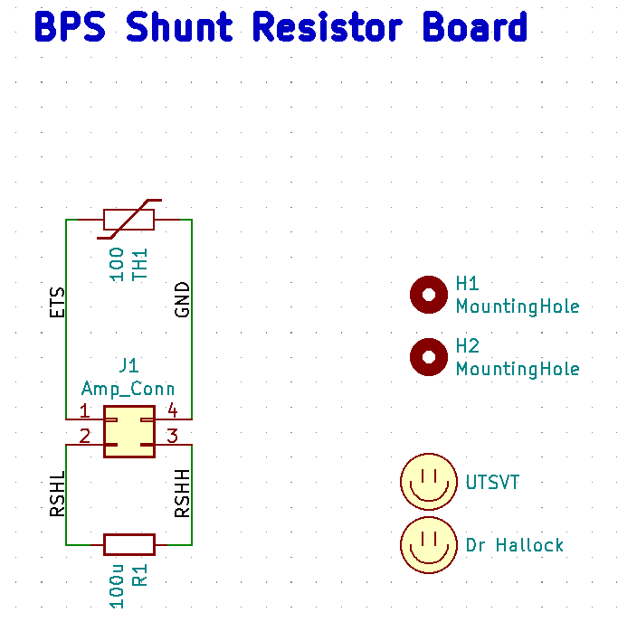
BPS Shunt Resistor Board Schematic
Dimensions: 37.592mm by 32.512mm
- Requirements/Constraints:
This board is required to fit in the molded enclosure on the shunt resistor. This molded enclosure is 40.1 ± 0.2 mm by 35.1 ± 0.2 mm (in inches, it is 1.580 ± 0.009 in by 1.380 ± 0.008 in).
The headers and mounting holes on this board must align with that of the molded enclosure of the shunt resistor.
- Design Choices:
This board had dimensions just slightly smaller than that of the molded enclosure on the shunt resistor. This prevented the board from moving around too much within the molded enclosure and made placement of circuit parts easier.
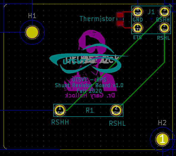
BPS Shunt Resistor Board Layout
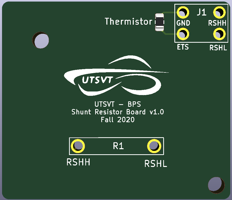
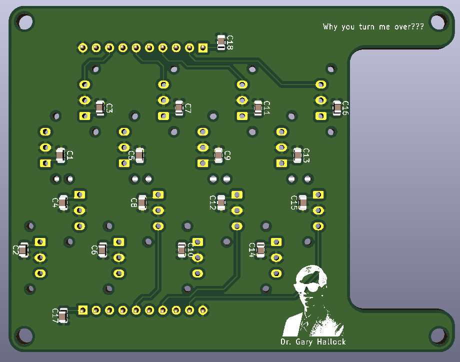
Front of BPS Shunt Resistor Board Render
Back of BPS Shunt Resistor Board Render
- Additional Considerations:
The shunt resistor must be oriented such that a positive current corresponds to discharging the battery.
BPS Test Board
Overview
- Brief Description/Purpose:
The purpose of this board is to emulate the battery modules for minion board testing
Context
Location of the Board: it’s tool for testing the minion boards so it doesn’t have an exact location in the car
List of I/O and Connections:
- Power +5V
Input from power bench
- GND
Input from power bench
- 1-11(J23 and J24)
Output to the Minion board
- GND(J23)
Output to the Minion board
Schematic
Main
- What does this circuit do?
It provides a nominal voltage, undervoltage, and overvoltage to the minion boards
- Why do we need it?
To test if the minion boards work properly and not to mess with the battery
- List of Circuit Components
- RFM-0505S (constant converter
Description: changes +5V to +3.3V
Why is it necessary: to provide a nominal voltage to the minion board
Justification for selection of specific part: this converter provides us with specs we needed for this board
- RFM-0505S (variable converter)
Description: +5V to undervoltage and overvoltage of +3.3V
Why is it necessary: to provide an undervoltage and overvoltage to the minion board
Justification for selection of specific part: this converter provides us with specs we needed for this board
- Associated passives/components:
Potentiometer_THT:Potentiometer_Piher_PT-6-V_Vertical_Hole
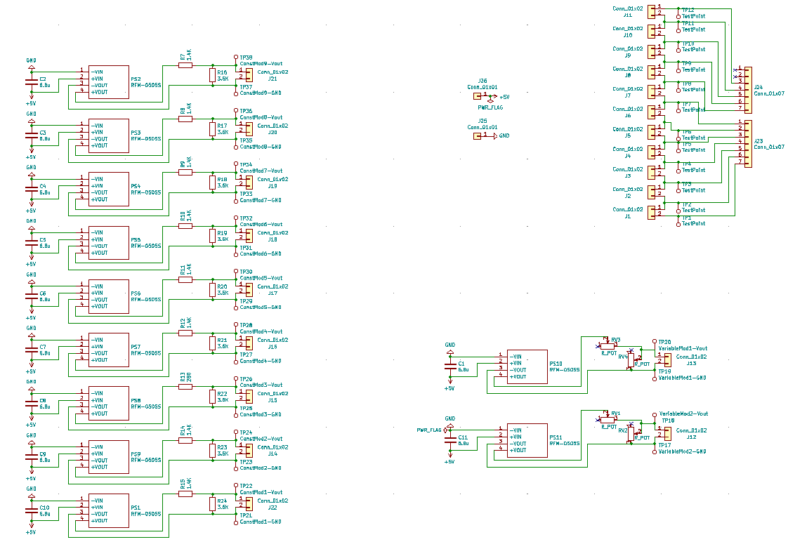
BPS Test Board Schematic
Dimensions: 91.00mm by 94.00mm
- Requirements/Constraints:
Emulate 8 battery modules in series
Possess the ability to undervoltage and overvoltage specific modules independently of other modules
- Design Choices:
Compacting components to make the board the smallest it can be
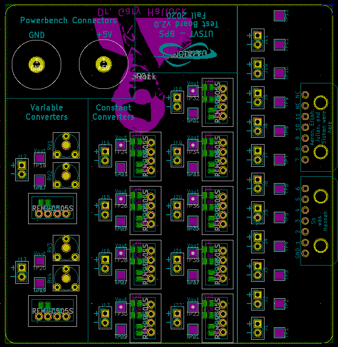
BPS Test Board Layout
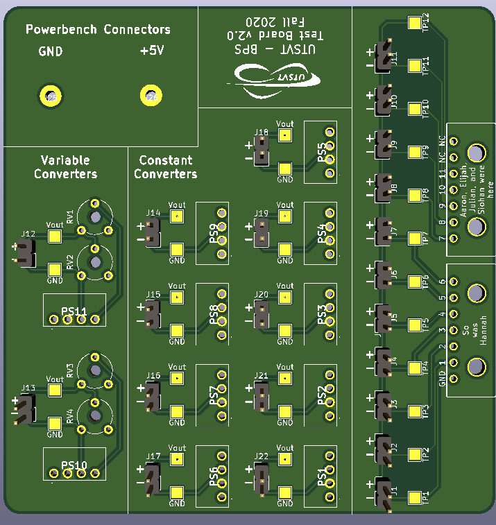
Front of BPS Test Board Render
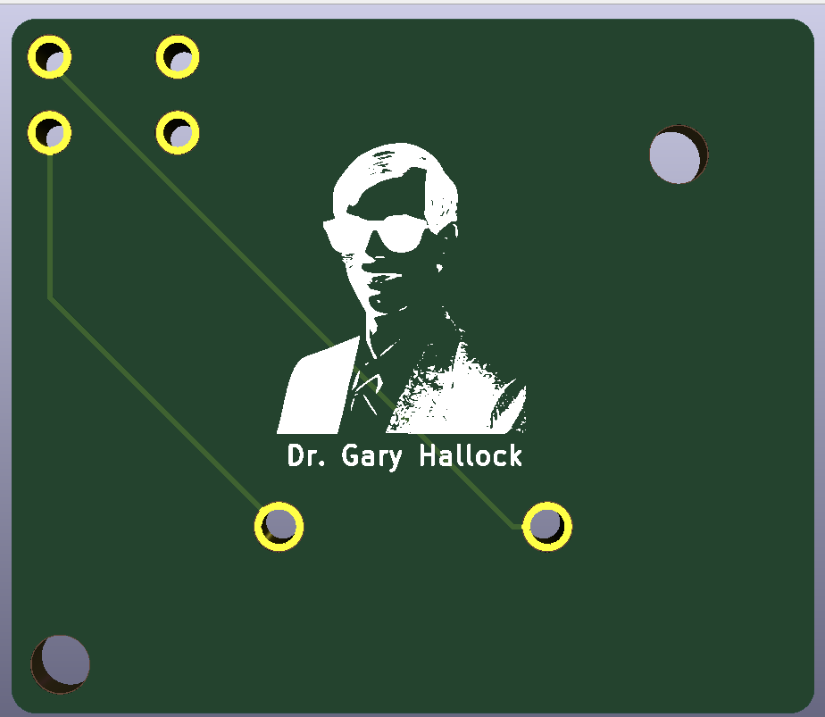
Back of BPS Test Board Render
BPS Scrutineering Board
Overview
- Brief Description/Purpose:
This board will be used during the scrutineering process for the American Solar Challenge race. It will be used to demonstrate that the BPS is functional by proving that the BPS executes the appropriate measures in an overvoltage and undervoltage state. The battery modules will be disconnected from one BPS Minion Board and will be connected to this board in its place. The board will be connected to an external power supply, which will be used to simulate a normal, overvoltage, and undervoltage state. This board will induce an overvoltage and undervoltage state to trigger the BPS without affecting the batteries.
Pertinent Regulations
Regulation |
Description of Regulation |
How Regulation is Met |
8.3 |
Protection circuitry: proof is required at
scrutineering that the protection system is
functional and meets manufacturer’s
specifications. Testing procedures will be
provided, and the protection system design
should allow for such testing.
|
This board is intended to help the BPS pass
scrutineering. It is supposed to help in the
testing procedures to demonstrate that the
BPS system is function and meets any
specifications
|
Context
Location of the Board: The board is not located in the car.
List of I/O and Connections:
- Up to 14 Battery Voltages
Input from the Battery Pack
- Up to 14 Minion Board Connections
Output to the BPS Minion Board
Schematic
Main
- What does this circuit do?
This circuit serves as a ‘middle-man’ during the scrutineering process. It connects the batteries to the BPS Minion Board. On each connection, there is a banana jack connector for the race official to connect a power supply to. When doing so, the official can disconnect the one battery connection using the DIP switch and then control the voltage being provided to the BPS Minion board through the external power supply.
- Why do we need it?
This is needed for the solar car to pass the scrutineering process. One test that will be done is to ensure that the BPS is functional.
- List of Circuit Components
- CT3149 Banana Jack Connectors (x14)
Description: These banana jack connectors can be used to connect to an external power supply.
Why is it necessary: Regulations necessitate banana receptacles during the scrutineering process
Justification for selection of specific part: The part was cost-effective, not too large, and allowed for easy soldering.
- Omron A6S-7102-PH DIP Switch (x14)
Description: This switch can be used to individually disconnect a battery module so that a power supply can be connected instead.
Why is it necessary: This is to ensure that the batteries are not impacted in any way by the connection to a power supply.
Justification for selection of specific part: This had the appropriate number of connections and met the team’s needs in terms of functionality.
- Associated passives/components:
4 1x7 connectors to connect to the BPS Minion Board and to the battery modules
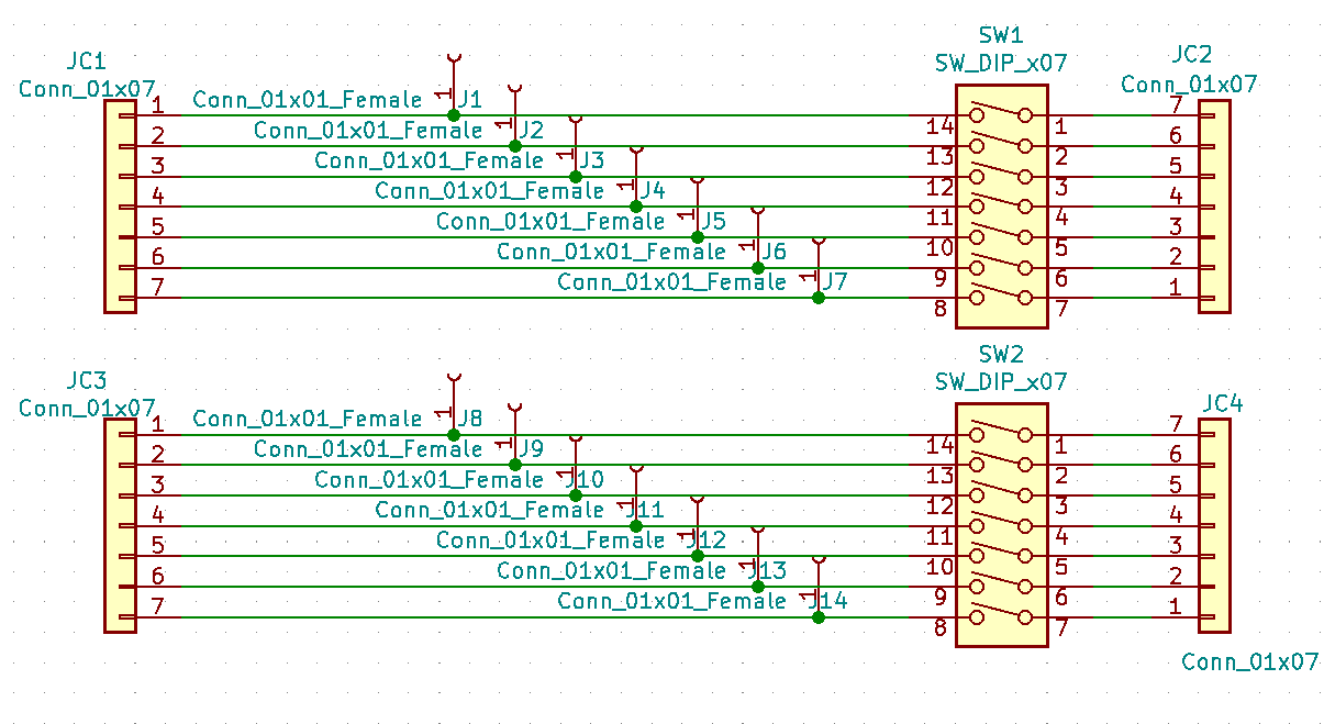
BPS scrutineering Board Schematic
Dimensions: 94.400mm by 74.676mm
- Requirements/Constraints:
The board should be space-efficient, intuitive, and easy to use. The parts should be appropriately labelled.
- Design Choices:
The banana jack connectors were placed in a space-efficient manner. However, due to the compactness of the connectors, a connector key was placed in the silkscreen layer at the bottom of the board in order to identify each connector.
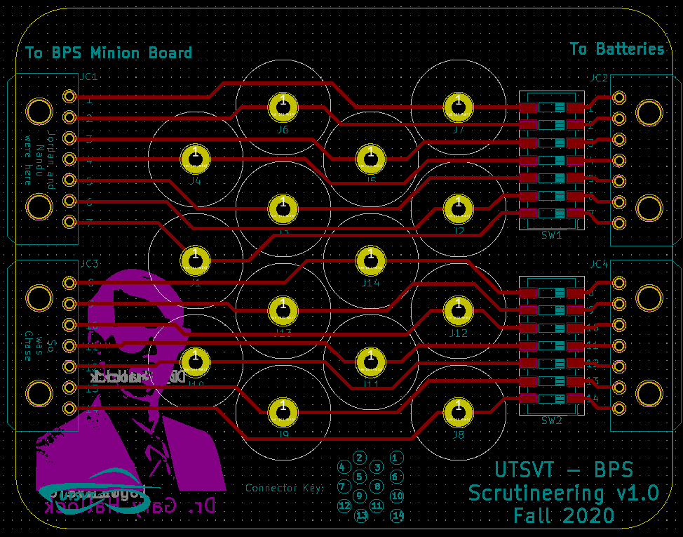
BPS Scrutineering Board Layout

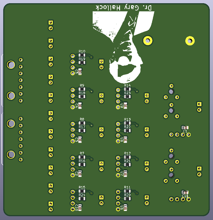
Front of BPS Scrutineering Board Render
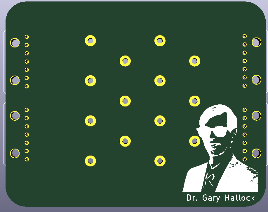
Back of BPS Scrutineering Board Render